TECHNICAL DATA:
Extrusion capacity :According
Number of candy ropes : 1-4 rope(s)
Extrusion screw diameter : 100mm
Infeed roller diameter : 110mm
Drive power :2x5.5kw
Water-heating power : 3x6kw
Protective system :IP55
Speed adjustment range :1:29
Water consumption :300 liter/hour
Net weight :2300kgs
Dimension :2600X1570X1840mm
Power absorbed :440V,3 Phase, 50HZ
SAFETY INTRODUCTION
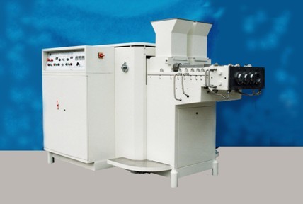
This co-extruder type TW-EX100/2BG is designed and constructed for extrusion of bubble gum or chewy candy ropes, which is reliable in safety and convenient for operation, In electrical side, it controls in concentration while in mechanical side, it accommodates in a closed structure.
The shutdown procedure by pressing the OFF button on the control panel must be carried out before all installation, operation, conversion, maintenance and repair works.
In addition, the following instructions must also be observed:
1. The hopper inside must be carefully checked before every start-up of the machine to keep away from foreign matters to prevent the machine from damaging and to prevent the mass or candy from pollution.
2. Any tools or goods are not allowed to be placed onto the machine to prevent any lf them from entering into the hopper.
3. While feeding the mass into the hopper, attention shall be made not to stretch your finger into the hopper to avoid any accident.
4. The user of this machine must ensure that the working areas at or around the machine are kept clean and tidy through corresponding instructions and controls.
GENERAL DESCRIPTION
This CO-extruder type TW-EX100/2BG are used for the production of one or two coloured bubble-gum or chewy candy with normal production capacity of 600kg per hour and can continuously feed two to four sets of cut & wrap machines.
This machine is equipped with advanced electrical control system and mechanical conveying structure. On the control panel, there installed digital displays on which the set driving speed and water supply temperature are clearly displayed.
This machine has two-extrusion systems, Changing different extrusion dies can produce two coloured products and different shapes of mass ropes, for instanceˇ° ˇ±etcˇ
MAIN STRUCTURE
This co-extruder is constructed with the following components:
1. Frame
2. Gear reducing box
3. Extruder
4. Extrusion Head
5. Electrical Appliances
Each component is detailed as below:
FRAME
The frame is the basis of the machine, which is adoptingˇ°frame styleˇ±structure, and is welded together with the protection covers, thus, is firm and stable.
GEAR REDUCING BOX COMPONENTS
There are two sets of Gear reducing box components, which is driving by two sets of A.C. SEW asynchronous motor of 440V, 3 phase, 50Hz and 5.5kw via a gear unit. Gear reducing box and the motor are both mounted on the frame, with one cross-shaped coupling connects them.
Gear reducing box is composed of four groups of gear bearing and bridge gear, which distributes the power to the infeed roller and extrusion screw separately.
Two sets of variable speed controller controls the speed of two pairs of infeed roller and extrusion screw accordingly, which can infinitely adjust the reducer speed within the range of 0ˇ˘~27 rpm.
The speed ratio between motor and extrusion screws is 1:1. Infeed rollers are decelerated through 16:32 gears and its speed is half of the reducer.
Setting of the motor rotating speed shall be decided by the user taking the two factors of intactness of extruded ropes and extrusion efficiency into consideration.
EXTRUDER COMPONENTS
Extruder components undertake two functions of mass infeed and extrusion, which includes ˇ°upper seat ˇ±and ˇ°lower seatˇ±. The bottom face of the ˇ°lower seat ˇ±is fixed on the frame by screws. One side is positioned with the side face of gear reducing box using two pieces of position-case each which allows the good coincidence of the two axis, then use two long rod to tighten, forming a whole part. The other side is connected with the extrusion head, forming a passage of power transmission, mass feeding, mass extrusion and extruded-ort.
The Co-extruder is equipped with two extrusion barrels mounted on one frame, each barrel is mounting with two¦Ő110mm infeed rollers and two¦Ő100mm extrusion screws. The two infeed rollers rotate in opposite directions pressing the mass into the extrusion screws and the later moves spirally pushing the mass to extrusion head.
The ˇ°upper seat ˇ±and ˇ°lower seat ˇ±of the extruder are also designed with S-type water channel that connects with the water heating system through flexible hoses and automatic heating can be carried out via water circulation inside the S-channel. When the mass extrude through the barrel, with the help of periphery temperature, its fluidity reaches the best state.
The ˇ°upper seat ˇ±of the extruder can be hinged over by loosing the related nuts, depending on the central axle as rotary center, insert one rod into the process hole at the location of the hopper and push upward. By doing so, the extrusion screws and its barrel can be easily cleaned.
EXTRUSION HEAD COMPONENTS
The extrusion head is fixed onto the extruder side by boring axle and bolts which is easy for mounting and dismantling.
There are two mass entrances and upper and lower horizontal passages receiving The extruded masses colour-wisely. 2ˇ«4 die-holes are designed on the extrusion head(numbers of holes may also be decided by the user when placing order).
At the front of the extrusion head, there also designed with S-type water channel connecting with the water heating system. The machine can only started when heating of this extrusion head reaches the required temperature, which is electrically controlled by inter-lock circuit, to ensure the mass fluidity reaches ideal state.
ELECTRIC APPLIANCES
Main driving of the machine is carried out by two SEW 3 phase 440V asynchronous motors through two gear reducer. Two AC. Variable speed controller together with main driving motors are introduced to infinitely adjust the extrusion speed.
Each set of extrusion screws is assigned with a speed controller to regulate the ratio depending on various raw materials to be extruded. ˇ°Speed Upˇ±or ˇ°Slow Down operation is achieved by a speed controller when the ratio has fixed.
The extruder is equipped with three temperature controllers with temperature display. All electric components and operating device are positioned at eyeˇŻs level. All contactors, relays and fuses are installed n the electrical cabinet.
UNPACKING OF THE MACHINE
All the machines are delivered with sea-worthy wooden packing. It is suggested to unpack the machine at the vicinity of the installation location. At the time of unpacking, remove the dust-protection coat and, the followings must be carefully checked and well recorded:
ˇö Any damages or broken to the wooden packing;
ˇö The actual delivered goods match with those listed in the packing list, such as special tools, components, spare components and accessories;
ˇö Any damages to the machine.
If any damages to the machine of any losses of tools, spare components and accessories are found, please timely inform manufacturer or general sales agent in writing.
!CAUTIONŁşANY DAMAGES TO THE MACHINE CAUSED BY
INCORRECT AND CARELESS UNPACKING OR ANY
LOSSES HAPPENED AT USERˇŻS STORAGE ROOM SHALL
BE AT USERˇŻS OWN RESPONSIBILITY.
INSTALLATION OF THE MACHINE
The machine may only be installed by TW specialists, Connection to the mains is to be made by electricians.
Safety regulations and dangers
ˇö Do not work under swinging load.
ˇö The bearing strength and levelness of the floor at the place of installation must be proved by a static engineer.
ˇö The conditions necessary for the correct functioning of the machine at the place of installation are to be ensured.
The components dismantled for transportation are again fitted to the machine.
WATER HEATING SYSTEMS
Water heating systems are composed of water tanks, magnetic valves, water pumps, heating elements, temperature controllers and water level gauges, etc. Totally 3 water heating systems are provided to this machine, in which one system(NO.1 water tank) is provided for extrusion head, and the other two systems(No.2 & No.3 water tank) are provided for two extruders separately. Inside each water tank, one 6 KW heating tube is installed to heat the water. Over-heating and water-shortage are automatically opened and closed by the magnetic valve. Water level gauge is used to detect the water level inside the water tank which cooperates with the temperature controller, timely give orders about the water level and temperature. Heating, over-heating and water inlet. etc., are carried out timely and correctly.
It is recommended to set the water temperature inside the water tank at 50ˇć. The user may self-decides the best temperature according to the practical experience and mass extruding status. Due to the influence of hot inertia, the over-heating should be restricted, normally set between ˇŔ1ˇ«3ˇć. The temperature and of difference in temperature can be set at the temperature display board on the main control panel.
ELECTRICAL CONNECTION
Main cable and control cable wiring terminal are located below the electrical cabinet. The door of the cabinet is locked in general. Control panel is installed at top of the electrical cabinet.
The feeder line connects the 25mm2 wiring terminal located at the right downside of the electrical cabinet with markingˇ°L1,L2,L3ˇ±. The electric of the machine is designed as 440V, 3phase,50Hz.
The two sets of asynchronous motor are of 5.5KW each 3 phase 440V. wiring method is delta-connected(ˇ°ˇ÷ˇ±).
The 6KW heating tube inside the three water tanks is 3 phase 440V, star-connected(Y-type) wiring method.
The total power of this machine is 32KW.
The minimum cross-section of the feeder line should be ˇÝ25 mm2 multi-strand copper. Grounding wire shall connect with the special grounding bolt at location of feed line entrance with marks, which should have a minimum cross-section of 4 mm2 multi-strand copper.
Before starting the machine, careful check shall be carried out to ensure electrical insulation, power supply specification and grounding meeting requirement.
START UP AND SETTING
(1) Open the water inlet valve;
(2) Open the door of electrical cabinet, switch on the main power(KY1);
(3) Turn the ˇ°Emergency Stopˇ± button (K) in the arrow direction. This button will automatically leap out to connect the circuit (pressed down the button will be automatically locked to stop the machine).
(4) Press the KY1 button to connect the main power, the power indicating lamp RD1 is lit, the power indicating lamp on HK1ˇ«HK3 lit and ˇ°NO WATERˇ± indicating lamp is on, it means short of water. At this moment, the water tanks will be filled with water automatically by the magnetic valves. Automatic heating will be allowed when in low water level; while in high water level, the magnetic valve will automatically shut off the water source and the ˇ°NO WATERˇ± indicating lamp on HK plate will be off thus the water tank is full.
(5) Connect Q4ˇ«Q7 switches and turn K1 switch, the water tanks will be automatically heating and circulating by the temperature controllers.
(6) Water Temperature Setting (Please refer to following drawing)
Water temperature setting is performed on the Temperature controller (TM1~TM3). On the above sketch, the temperature indicating switching key ˇ°1ˇ± is for temperature display, down key ˇ°2ˇ± is setting decrease and up key ˇ°3ˇ± is setting increase.
Press the key ˇ°1ˇ± first time to show the present water temperature (actual temperature of the water tank).
Press the key ˇ°1ˇ± second time to set the temperature . Set the by key ˇ°2ˇ± and ˇ°3ˇ±. This set shall be the working temperature .
Press the key ˇ°1ˇ± third time to set temperature input shift . Set the by key ˇ°2ˇ± and ˇ°3ˇ±. In general, this shall be within 1~3.c or so.
(7) Upon the temperature of extrusion head reached the set , the main motor may start to work. Since the electrical is inter-locked. If the extrusion head does not reach the set temperature, the main motor has no way to start. This is to prevent the machine from damaging caused by overload of the cold start-up. This procedure must be also followed when stop the machine during the working period.
(8) Check TM1 temperature controller to see whether the displayed temperature reached the set or not. If reached, starts to operate the variable speed controller.
(9) Start the main motor:
A. press down KY1 for 2~3 seconds ( to release the inter-locked circuit) to energize the two variable speed controller, the blue indicating lamp on KY1 will be lit to show the contactors KST1 & KST2 connected.
B. (The two motors may start separately) Press down KY3 or KY5 to have the KST3 & KST4 connected, the two blue indicating lamps also lit. The figure shown on the two temperature controllers is 0.
The first set speed up press KY7, speed down press KY8;
The second set speed up press KY9, speed down press KY10;
Both two sets speed up press KY12, speed down press KY11.
CHANGE DIES
This co-extruder is applied for any mass extrudable, such as bubble gum and chewy candy. User shall specify the dimension and shape of the gum embryo at the time of placing order for which extrusion dies are dependable. If user wishes to change the dimension and shape of the gum embryo in the future, he may also place orders for the extrusion dies only.
However, the range of dimension of the gum embryo shall be:
Width ¨Q 22mm
Height ¨Q 8mm
MAINTENANCE
For maintenance purpose, special attentions shall be made to the followings:
(1) If any abnormal noise sent out from gear reducing box, the possible cause is that one bearing of some component may be damaged, change it with same specification.
(2) If big noise sounded inside gear reducing box, whether any foreign matter sneak into the box or gear damaged caused by other reasons.
(3) If any oil leakage was founded from any part of gear reducing box, possibly the sealing washer/ring was damaged, replace it with same specification.
(4) If water leakage was founded at any connecting point of the water tank, change new tape and retighten it.
(5) If the water tank was not heating, possibly heating tube was broken, replace it with a new one.
(6) If the magnetic and heating was abnormal, the rod of water level gauge may corrode, replace it with a new one.
(7) For big repair requiring lift-up the gear reducing box, take care that more the extended axle of the gear box backwardly to loose the pin and the extrusion screw. Otherwise the components may be damaged.
LUBRICATION
The motor reducer and the gear reducing box are both adopting closed oil bath lubrication systems, which is recommended to apply with industrial gear oil with viscosity of 150. First oil change shall be executed after 30 days running. During operation period, oil change shall be required at 6 months interval.
The inner gears at connecting point of gear reducing box and extruder, it is suggested to apply with No.2 Li-based grease at appropriate time.
Both side of the infeed rollers at location of ball bearing also apply with No.2 Li-based grease at appropriate time.
|